After reading this article you will learn about network construction and development.
Network Construction:
Activity:
A project consists of several activities or operations, and the project is said to be completed when all such activities are completed. Activity is the actual performance of a task. This consumes resources i.e., time, manpower, space, material, money etc.
Event:
ADVERTISEMENTS:
It is a start or completion of task. In other words, an event is an instantaneous point of time at which activity or activities start or finish. This does not consume time or resources.
Following example will clarify the difference between an event and activity:
Start Machine Installation: An event
Machine Installation: An activity
ADVERTISEMENTS:
Completion of Machine Installation: An event
Some more examples to distinguish between an event and an activity are given below:
Example 1:
T or F has been entered for True or False against the statement given below:
ADVERTISEMENTS:
(i) Performance of specific task is am event. (F)
(ii) The beginning and ending points of activities are called events. (T)
(iii) Activities consume resources and time whereas events do not. (T)
(iv) Performance of a specific task is an activity. (T)
ADVERTISEMENTS:
(v) Events are an instantaneous point in time at which activities begin or end. (T)
(vi) Event consumes resources and time whereas activities do not. (F)
(vii) Turning the job on lathe is an activity whereas job turned as an event. (T)
C.P.M. Systems:
Mainly there are two systems:
ADVERTISEMENTS:
1. AOA system i.e., ‘Activity on the Arrow system’.
2. AON system, i.e., ‘Activity on the Node system’.
1. AOA System:
In the ‘Activity on the Arrow system’ (Arrow Diagram Method) is an activity graphically represented by an arrow as shown on the left side of Fig. 28.10. 
The tail end of the arrow represents the start and the head of the arrow represents the finish or end of the activity. The description of the activity is written above the arrow. Events are represented by circles or nodes at the beginning and the end of activity arrow as shown on the right hand side of Fig. 28.10. An event is a function of two or more activities.
ADVERTISEMENTS:
The simple network shown in Fig. 28.11 clarifies the representation of activities and events. In any large project, certain activities have to be completed before the commencement of certain other activities.
Some of the activities can be started concurrently. If all the activities and events in the project are graphically represented showing their interdependencies, then a Network is obtained. Such a network represents the plan for the entire project.

Rules for Network Construction:
ADVERTISEMENTS:
1. The length of the arrow bears no relationship to the time which the activity takes or the resources which the activity consumes.
2. The arrow in a network identifies the logical conditions of dependency. The geometry of arrow diagram is of no significance except that it should be aesthetically pleasing.
3. The direction of the arrow indicates the direction of work flow. The normal convention is to go from left to right.
4. All networks are constructed logically on the principle of dependency.
5. No event can be reached in a project before the activity which immediately proceeds is completed. Similarly no activity can be started until the event which immediately precedes it has been reached.
ADVERTISEMENTS:
6. Every activity in the network should be completed to reach the objectives of the end event.
7. No set of activities can form a circular loop.
Numbering the events and activity identification:
Rules for numbering events and identification of activities are as follows:
(a) All events must be numbered.
(b) The same number cannot be used for more than one event. This is necessary in order to identify each activity.
ADVERTISEMENTS:
(c) Events can be numbered in any other system but usually forward numbering system is more familiar. In this method, first event in the network is numbered 1(or zero) and the second 2 and so on, in such a way that the event number at the tail of each activity arrow is always smaller them the event number at the head of that activity arrow. This implies that the final event of the network will have the large number and will be equal to the number of the nodes in the network.
Fig. 28.12. Illustrates the forward numbering of events and activities identification in a network.

A dummy is an artificial activity introduced in a network to:
(i) Maintain a unique numbering system for the different activities.
ADVERTISEMENTS:
(ii) Keep the logical sequence of activities and their interrelationship correct.
A dummy is shown by a dotted arrow as indicated in Fig. 28.13.
![]()
Dummy does not consume Time or Resources.
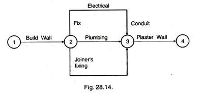
Consider the network shown in Fig. 28.14. Three of the activities in the network, i.e., fixing of electrical conduits, plumbing and joiner’s fixing bear the same number 2-3. Thus the identification of activities is not unique. This situation can be corrected by using dummy arrows as shown in Fig. 28.15. Now, fixing electrical conduits is identified by 2-3, plumbing is identified by 2-5 and joiner’s fixing’ is identified by 2-4. Activities 3-5 and 4-5 are dummies.

Consider the network shown in Fig. 28.16. Let EFG represent the shuttering on three bays of a retaining wall and L, M and N, the corresponding concreting operations.
In view of the nature of the activities, it is reasonable to presuppose that in each case, the shuttering has to precede concreting. As regards the labour, only one forward crew and one concreting crew are available. Dummies are used here to represent the restraint and consequent interdependency.

2. AON System of Network Representation:
In the ‘Activity on the Node’ System, activities are represented by the circles or nodes and arrows are used to show only the dependency relationship between the activity nodes. Fig. 28.17 gives some AOA networks against which corresponding networks in the AON system are shown. It can be noticed that dummy arrows are eliminated in the AON system.
Example 2:
ADVERTISEMENTS:
Select appropriate words /phrases from those given in parentheses to complete the statement below:
(i) An activity is represented by…… whereas an event is represented by…… in the activity on the arrow system of network representation, (a circle, an arrow, head of an arrow, tail of an arrow).
Ans. [An arrow, a circle]
(ii) An activity is represented by……. whereas…. are used for representing dependency relationships in the activity on the node system, (a circle, an arrow, arrows, head of an arrow, tail of an arrow).
Ans. [a circle, arrows]
(iii) Activities are represented by the….. and the activity descriptors are usually written in the past tense and are placed inside…. representing events, in the event oriented network, (circle, arrows, head of an arrow).
Ans. [arrows, circle]

Example 3:
Match the items given in Col. A with the corresponding ones in Col. B in the following:


Example 4:
State which of the following statements fully and correctly defines a network as applied to production jobs:
(i) A network is a graph.
(ii) A network consists of activities.
(iii) A network is a graphical representation of a sequence of activities that must be completed to reach the end objective of a project showing the inter-dependencies between the activities.
(iv) A network also known as a bar chart where operations are listed vertically one below the other and the time required for completion of these activities is plotted on the horizontal axis.
Ans. [(iii) is correct]
Example 5:
Match the network diagrams given in column x with their corresponding logic in column y. (Figs. 28.19, 28.20).


[In column y, item 1 represents Fig. 28.21, item 2 represents Fig. 28.19, item 3 represents Fig. 28.20 and item (4) represents Fig. 28.22]
Network Development:
In developing a network diagram, the following questions must be asked for each operation:
(i) What activity must immediately precede this operation?
(ii) What activity should immediately follow this operation?
(iii) What activities can take place concurrently with this operation?
Based on these questions, each activity is connected with one or several of the ways as shown in Figs. 28.23 to 28.26.


In the first instance, it is important to prepare a network that represents the time logical dependency of activities on one another assuming availability of unlimited resources.
It is useful to show each arrow with a horizontal portion being used for activity description that should always be included every network. This layout with horizontal lines imparts not only nearness but also permits the network to be separated into a series of horizontal zones representing either separate sections of the project or perhaps different types of work such as design, contracting, civil works etc.
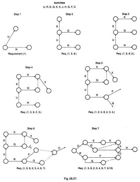
Example to illustrate Network Development:
The following are the activities and the logic for a project:
Logic (Fig. 28.27):
1. U and R can be carried out at the same time. They represent the beginning of the job.
2. After E follows K.
3. X depends on Q and K.
4. Neither F nor G can be started before R is completed, but they can be concurrently performed.
5. E and Q follow U.
6. Q must be carried out before J.
7. C depends on the completion of F and G.
8. E and Q can be executed at the same time.
9. H can only be started when C, X and J are finished. 10. H is the last activity.
Steps 1 to 7 in Figure 28.27 illustrate the development of net-work for the above logic.