This article throws light upon the top fourteen input devices used in a computer. Some of the input devices are: 1. Punched Cards Input 2. Paper Tape Input 3. Magnetic Tape 4. Magnetic Disk 5. Disc Systems (Floppy) 6. Winchester Disk 7. Keyboard 8. Terminals 9. Mark and Character Recognition 10. Optical Mark Reading (OMR) 11. Optical Character Recognition (OCR) and Other Few.
Input Device # 1. Punched Cards Input:
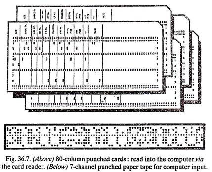
The standard present day punched card is a piece of thin card board measuring 3/8 inches x 3 ¼ inches. It is divided horizontally into 12 rows and vertically into 80 columns. A particular character is represented by a unique pattern of holes punched into one column (Fig. 36.7).
Cards are prepared by a person typing on the keyboard of a machine known as a Card punch. The deck of cards thus prepared (and then verified) can be read into the computer by a peripheral device known as a card reader at speeds of up to 30 cards per second.
ADVERTISEMENTS:
Advantages:
1. Card codes are universal.
2. A card may be easily added to, inserted, removed or replaced from a deck of cards.
3. Cards may be processed off-line (that is on machines not connected to the computer) e.g., sorted, merged, collated, reproduced.
ADVERTISEMENTS:
Disadvantages:
1. Rarely all card columns are used.
2. A card reader is a relatively slow input device.
3. Require verification—additional equipment.
ADVERTISEMENTS:
4. It is relatively expensive.
Input Device # 2. Paper Tape Input:
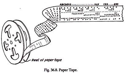
Information is represented in a machine readable form as a pattern of holes across the width of a strip of paper tape (Fig. 36.7 and 36.8).
The tape itself is typically one inch wide, successive characters being represented by a pattern of up to eight holes at a spacing of ten characters to the inch. The tape is prepared on the keyboard of a machine known as a paper tape punch.
ADVERTISEMENTS:
When all the tape has been prepared (and this usually involves a verification process to check that the correct data has been punched) the information on the tape can be read by a paper-tape reader operating with the help of light beam and photo electric cells.
The light passing through the hole in the tape activates the photoelectric cell. Paper tape reader reads the data quickly upto speeds of 2000 characters per second. Paper tape can be thought of as being a Continuous punched card. This presents advantages such as the fact that no individual record can be lost or put out of sequence because (unlike punched cards) all are on the continuous tape.
However, paper tape is more difficult to correct and is less flexible for sorting etc. The paper tape punch is less expensive than a card punch. The paper tape input is frequently transcribed to magnetic tape in a paper tape to magnetic tape run before further processing is performed on the data.
Input Device # 3. Magnetic Tape:
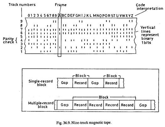
Magnetic tape consists of a plastic base coated with an iron oxide coating. Tape measuring 1/2″ wide is most common (Fig. 36.9).
Magnetic tape is very effective and inexpensive storage and very widely used. The recording of data on magnetic tape is similar in concept to a home tape recorder. Writing (recording) on the tape destroys the previous contents; reading may be repeated, since it does not alter the contents. The information is retained on the tape in the form of magnetized and non-magnetized spots (representing 1s and 0s) which are arranged in tracks, normally nine, running the length of the tape.
To represent a character in tracks, special codes are needed. Data is physically stored on the tape in blocks. The blocks are separated by an inter-block gap. A parity bit is included on the tape for checking purposes. Several methods, all quite similar, are used to drive the tape past the read-write heads and to permit the tape to be started and stopped quickly. A vacuum operated tape unit is shown in Fig. 36.10.
As shown in Fig. 36.10 the tape runs from a supply reel to a take-up reel via two vacuum chambers and the read-write head. The two vacuum chambers are designed to take up slack tape, acting as buffers to prevent the tape from snapping or stretching when starting from a stationary position or slowing down from full speed. In addition, magnetic tape is widely used to back-up information on magnetic disk. The use of cartridge tape for this purpose is associated particularly with microcomputer systems.
Input Device # 4. Magnetic Disk:
In shape a magnetic disk resembles an LP record. A disk pack consists of six or more disks mounted about ½” apart on a central hub which rotates, spinning the disks at speeds of 60 or more revolutions per second. Information is recorded on both sides of each disk as a series of magnetized or non-magnetized spots.
ADVERTISEMENTS:
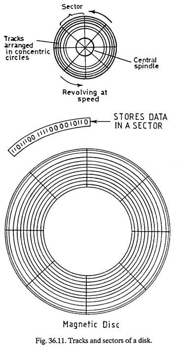
As with magnetic tape, the information on magnetic disk can be accessed again and again and when fresh data is recorded it simply replaces the existing information. On a magnetic disk, information is stored on tracks arranged in concentric circles (Fig. 36.11) with each character represented by a pattern of bits in sequence on one track. Although varying in length, each track contains the same number of characters.
Each track is normally subdivided into sectors and information is accessed by track and sector address (80; 4, that is 80th track and 4th sector). The diameter of the magnetic disk is 14″ and there may be several hundred tracks per surface (400-1600) each with a storage capacity of thousands of characters.
ADVERTISEMENTS:
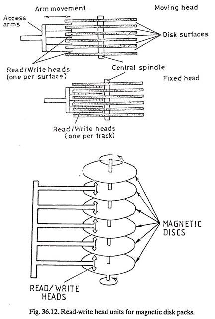
Disk packs are potentially very high capacity storage devices typically in the range of 20 to 1000 megabytes. There are two types of read/write head units for magnetic disk devices – a moving head unit and a fixed head unit (Fig. 36.12).
In the moving head unit, the head moves horizontally across the surface of the disk so that it is able to access each track individually. There is head for each surface and all the heads move in unison. Exchangeable disk packs are only associated with moving head units.
A fixed-head unit has one read/write head for each track, as a result of which, no head movement is needed and information is therefore traced more quickly. The heads do not have direct contact with the disc surface but rest on a cushion of air. The air movement caused by the revolving disk forces the head to fly about 1/400th of an inch from the surface.
Input Device # 5. Disc Systems (Floppy):
1. Disc systems take many forms which are commonly categorized as:
(a) Floppy,
ADVERTISEMENTS:
(b) Hard,
(c) Fixed, and
(d) Exchangeable.
Floppy and hard relate to the nature of the base material upon which the magnetic material is coated. If it is constructed from flexible plastic material the term floppy is used. If the material is rigid the term hard is used. Floppy systems tend to be much cheaper, not be so critical in their manufacturing tolerances but also have a much slower data transfer rate and smaller data capacity than hard disc systems.
Floppy disks tend to predominate in micro-computer systems where the requirement for large, fast disk storage is not necessary. The floppy disc was developed in the early 70’s as a cheap and fast alternative to storage on magnetic tape. The disc is made of flexible plastic and coated in magnetic oxide. There are two recognized standard sizes, 8″ and 5 ¼ “, frequently referred to as diskette and mini-floppy respectively.
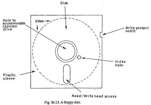
A more recent development is the 3½ ‘’ size. The capacity of an 8″ diskette is typically between 250 Kb and 1.5 Mb and that of 5¼ “, mini floppy is between 125 Kb and 500 Kb. For protection, the floppy disk is normally contained within a plastic or cardboard sleeve, often referred to as a cartridge (Fig. 36.13). The cartridge is readily loaded into and unloaded from a drive unit.
Unlike the moving-head read/write mechanism on magnetic disk drives, the heads on a floppy disc unit make contact with the rotating disc surface, when reading or writing and disks therefore get worn with constant use. The floppy disc is a low cost device particularly suited to supporting personal computer systems and for use with small business and word processing systems.
A fixed disc system is one in which it is not possible to remove the disk(s) from the drive mechanism. An exchangeable disc system is one in which the disk can be removed and replaced by a different disk. An exchangeable system allows for unlimited storage but only a part of the total can be accessed at any one time.
Input Device # 6. Winchester Disk:
Winchester disks are used to support mini-computers and micro-computers and they compete with floppies in the rapidly expanding areas of personal computing, word processing and business applications.
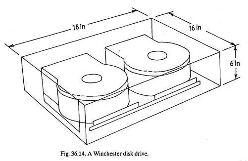
Winchester disks are hermetically sealed units, in which the read/write heads are designed to take off and land on the disc surface (Fig. 36.14). The disc is coated with a special lubricant which reduces the friction when the heads land and the sealed chamber prevents contamination from dust etc.
Winchester disks are available in 5 ¼ ” 8″ and 14″ sizes, but 8 inch is the most common. Storage capacities range from around 10 Mb to 456 Mb or more. There are also 3 ½” disks which can store 40 Mb or more. Winchester discs are fast and highly reliable, yet low priced. There is greater precision of alignment, an increase in the number of tracks on the disk surface and a higher storage density per track.
Input Device # 7. Keyboard:
ADVERTISEMENTS:
Keyboard entry of data is now the main method of input. It is probably the most user-friendly of all input devices. The keyboard is similar to the face of a typewriter, but uses a TV-type screen instead of paper. All keyboards are not alike. Because they talk to a computer, some keyboards have extra keys to perform communication commands. The alphanumeric keyboard is used to enter commands, text and parameter values.
To enable the key board to talk to the computer, a special code is employed. With IBM computers an EBCDIC (Extended Binary Coded Decimal Interchange Code) keyboard is used. Many other computer companies use an ASCII (American Standard Code for Information Interchange) keyboard.
N.B:
There are two types of keyboards, the EBCDIC and ASCII as explained above.
Along with the keyboard, a programmable function box is often used. Such unit contains from 16 to 32 function keys. When pressed, each key generates a unique code, providing two-way communication between the user and host program. Usually function keys are lighted, allowing the operator visual monitoring of what activity is taking place.
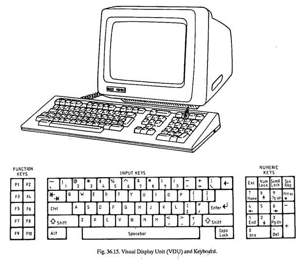
The keyboard of a personal computer has the following set of keys on the keyboard (Fig. 36.15):
ADVERTISEMENTS:
Function Keys (Leftward):
F1, F2, F3, F4, F5, F6, F7, F8, F9, and F10.
Input Keys (Centre Position):
Containing 1, 2, 3———– , A, B, C,———– X, Y, Z.
Control, shift, alter etc.
3. Number keys (Rightward position in Fig. 36.15)
ADVERTISEMENTS:
0, 1, 2, 3,………… 9, Esc, Num Lock, Del, etc.
Function Keys when BASIC in Run:
F1 ― List
F2 ― Run
F3 — Load
F4 — Save
F5 — Continuity
F6 ― LPT 1 (Line Printer-1)
F7 — TRON (Trace on).
F8 — TROFT (Trace Off).
F9 — KEY
F10 ― SCREEN
Function Keys with Operating Systems (MSDOS):
F1: Redisplays previously entered line, a character at a time. F1 key must be hit for each character.
F2: Enter F2 followed by a character. Screen will redisplay all of the previously entered line upto the character you entered.
F3: Redisplays the whole previously entered line.
F4: Enter F4 followed by a character. Screen will skip all of the characters in the previously entered line up to the character you entered.
F5: Stores the currently displayed line for further editing.
F6, F7, F8, F9, F10 are vacant under MSDOS.
Ctrl: The CONTROL key is always used with another key to perform a command or to select a particular function.
Shift: The shift key changes lower case letters to capital or upper case.
Alt: The ALTERNATE key is used with alpha typing keys to enter key words under BASIC.
Enter: The ENTER key is used to enter commands and/or responses into the system from the keyboard.
Caps Lock: This is toggle key. Hit the key once, and all letters typed will be in upper case (Capitals). When this key is depressed a red light will come. Hit this key again to return to lower case.
Esc: The ESCAPE key deletes the last line that the cursor is on for corrections, but the line is not removed from the systems memory.
Scroll Lock: SCROLL LOCK/BREAK is used in conjunction with the control key.
Prt. Sc.*: PRINT SCREEN will print on*Hit* simultaneously with the shift key, it will print all the data displayed on the screen as hardcopy printout from the printer.
Num Lock: The number lock is a toggle key. Hit the key once and the numeric key pad is activated. When the key is activated, a red light appears to indicate that the NUM LOCK is on. Hit the key again and numeric key pad is cancelled.
KEY: FUNCTION
1-9: With NUM LOCK activated, number ONE through NINE will be operative.
Del: DECIMAL POINT is used with numbers.
0: ZERO used with numbers
INS: MINUS is used with numbers.
+: PLUS is used with numbers.
When the NUM LOCK key is pressed, it cancels the numeric key pad.
These keys will become operative:
KEY: FUNCTION
9PgUp: Moves the display screen up one page at a time as long as the key is pressed.
8↑: Moves the cursor up.
7 Home: Moves the cursor back to the home position, which is the first character position located at the top left of the display screen.
6→: Moves the cursor to the right.
5: No function.
4←: Moves the cursor to the left.
3 PgDn: Moves the display screen down one page at a time as long as the key is depressed.
2 ↓: Moves the cursor down one line.
KEY: FUNCTION
1 END: Moves the cursor to the last character on the line.
Del: Deletes the character at the position where the cursor is located.
0-INS: Insert sets the keyboard into a word processing correctional mode. Characters can be entered for correction at the cursor position and all data will move one cursor position to the right. By pressing the insert key again you can exit from the insert mode.
SYS: Internal register of CPU which stores the data temporarily.
Spacebar: The space bar is used to put a blank (a space) in a line you are typing. Often blanks are used to separate what you type into the computer just as we use them to separate words in typing or writing.
Input Device # 8. Terminals:
A teletype writer terminal, sometimes called a tele-printer terminal ox a keyboard / printer terminal, usually combines a keyboard for manual input of information, with a printer for outputting a hard copy (printed record) of the input, system information and program results. VDUs (Visual Display Units) are the most common form of terminal-the information is displayed on the screen as it is typed. (Fig. 36.15).
Terminals may be connected to a computer in one of two ways. Some are connected locally by direct cable lines. This is known as hard-wiring. The second method is via a remote link, either by telegraph, telephone line, network or by micro waves. Both these methods permit the simultaneous linking of several terminals in several locations to one computer, with each terminal making use of the computer in turn.
This is known as Time sharing. Terminals are widely used for such tasks as stock control, entering orders, updating accounts and seat reservations. More recent developments are hand-held terminal entry systems and hand print pads.
Input Device # 9. Mark and Character Recognition:
This method involves the recognition of marks or characters, e.g., from work dockets, cheques, sales order entry forms and even printed text.
There are three types of recognition:
(a) Optical Mark Reading (OMR).
(b) Optical Character Recognition (OCR).
(c) Magnetic Ink Character Recognition (MICR).
These forms of recognitions facilitate the direct transfer of data from source document to the electronic form in which information is held in the computer. Where they are used, they eliminate the need for the laborious key- entry of data that is associated with terminal and key-to disk (magnetic disk) and key-to-tape (magnetic tape) systems.
Input Device # 10. Optical Mark Reading (OMR):
Optical mark reader is used to identify the presence or absence of certain marks on the card or form, for example, the water and electricity meter readings. Optical mark readers are available to scan forms/cards completed in pen as well as in pencil. The card is passed under a light source and the presence of a mark is detected by measuring very accurately the infra-red light levels. A mark reader may be able to detect coloured marks.
An earlier method known as mark sense reading relied on the conductivity of graphite to determine the presence of a portion blackened intentionally (using a soft pencil) as in the answer sheets of examinations involving exclusively objective type-multichoice questions. The examinee is asked to blacken the places on answer sheet corresponding the answers which he feels to be correct (answers).
Input Device # 11. Optical Character Recognition (OCR):
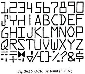
Optical character reader is a device for reading the documents. It may be capable of reading whole pages or merely one or two lines only. An OCR is used for reading various characters i.e., letters, digits and symbols optically. Generally the characters to be read must be machine (typewriter/printer) printed and of a special character design or fount (Fig. 36.16).
This is true that letters, digits and symbols are printed in variety of forms, shapes and sizes. But even then, there are certain characteristics which are peculiar and common to each character. The OCR recognizes each character as if it were made of a collection of minute spots, (Fig. 36.16).
After scanning a character, the pattern is matched against a set of patterns stored in the computer, whichever pattern is identified or nearly identified is said to be read. Patterns which are not identifiable by the OCR are rejected. OCRs find applications such as credit card billing and reading of pin code numbers in large post offices to sort mail geographically. OCRs are also used in banks, insurance companies, airlines etc.
Input Device # 12. Magnetic Ink Character Recognition (MICR):
Magnetic ink character readers (MICR) are used to read characters inscribed on (Bank) documents with a special ink containing magnetizable particles of iron oxide. This system uses highly stylized character shapes (Fig. 36.17).
E13 B is used principally for bank cheques. The code number of the bank, the customer’s account number, and the cheque sequence number are all pre-printed in the magnetic ink. When such a cheque is submitted in the bank, the amount of the transaction is inscribed on it. The cheque is read by MICR that recognizes the particular character from the variation in magnetic flux which is induced by the shape of that particular character.
The M ICR after verifying the characters, sends the data directly to the computer or to magnetic tape or disk for later input to computer. MICR system has the advantage that the forgery is impeded, however the cheque requires special printing device. The speed of reading MICR is around 1200 documents a minute.
Input Device # 13. CRT and Light Pen:
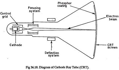
Data display devices use a cathode ray tube (CRT) to display data. Nearly all computer graphics terminals available today use the CRT as the display device. In CRT, a heated cathode emits a high speed electron beam onto a phosphor-coated glass screen. The electrons energize the phosphor coating, causing it to glow at the points where the beam makes contact.
By focusing the electron beam, changing its intensity, and controlling its point of contact against the phosphor coating through the use of a deflector system, the beam can be made to generate a picture on the CRT screen. The advantage of the CRT display is that an entire record can be displayed instantly.
A type writer device must type the record, a character at a time. CRT data displays are likely to be the dominant device in online systems having remote enquiry stations, as in Airlines. Data Display Devices may allow input via a keyboard or a light pen. If a permanent record is required of data displayed on the CRT, a command may be given to write the answer on the printer.
Light Pen:
A light pen is a graphic input device that allows an operator to interface directly with the CRT display. The hand-held light pen detects the light pattern of the picture on the CRT and sends an appropriate signal to the computer.
If the operator modifies the picture by drawing on the tube with the pen, the computer will automatically carry out all consequential corrections and calculations and will present the result for observation.
The light pen enables the operator to pick a point, character or vector on the CRT screen and to cause the system to take some action on the object picked. Repositioning or changing data on the screen is possible with the use of a light pen. The pen’s tip acts on the area that is touched on the screen.
Input Device # 14. Voice Data Entry (VDE):
Voice data entry is rapidly becoming a desirable key input function for CAD/CAM systems. There is no need for the operator to move hands or eyes to different control panels or key boards to enter information. Data is input via a voice-intelligent terminal. VDE technology represents an attempt to simplify the human-machine interface.
Under the proper circumstances, voice entry of information to the computer represents the easiest and quickest method of input. There is both, ease of use and efficiency, since a person can speak faster than he can type or write. A voice input system accepts spoken input. The system works by digitizing the waveform produced by a spoken word and storing the values as a bit pattern.
The waveform created by the spoken input is analysed, patterns are extracted and matched against pre-stored patterns to identify the input. Once identified, the appropriate coding is generated for handling within the computer. Before a voice input system can be used, it must first be provided with a vocabulary. The words and phrases the system is to recognize are spoken with the system operating in a so called training mode.
In this mode, the patterns are created and stored for future matching. A system may be trained to recognize both the voice of (one or more) operators and a given vocabulary for each operator, in which case, unwanted inputs or unauthorized speakers are rejected. The voice link to a system may be by microphone, telephone or radio communication.
Examples of applications of VDE are:
i. Programming NC machine tools,
ii. Data input for manufacturing information systems,
iii. Quality inspection,
iv. Inventory control,
v. Part identification, and
vi. Shop floor control data collection.
VDE has certain limitations also, for example:
(1) Most voice systems are speaker dependent, which means the system will not entertain input from everybody. It may not entertain even its actual user if his voice changes due to some temporary illness.
(2) A reasonable vocabulary is required to enter the data. Vocabularies are comparatively small, typically 100 to 300 words. In general as the size of a vocabulary increases, recognition reliability decreases.
(3) Each word spoken should be followed by a short break.
