
The different steps involved in process planning are: 1. Preparation of Working Drawing 2. Make or Buy Decision 3. Process Selection 4. Machine Capacity 5. Process and Equipment Selection Procedure 6. Selection of Material, Jigs, etc. 7. Preparation of Documents.
Step # 1. Preparation of Working Drawing:
A product is depicted by its drawing. A working drawing is a document complete in itself to manufacture a component or product. It shows component’s geometrical shape, its dimensions with tolerances, if to be machined, surface finish required, any heat treatment, surface coating if required, bill of material and any other information considered necessary so that the component can be manufactured and inspected without any difficulty.
An assembly drawing shows the complete product with all its parts in proper relationship. Subassembly drawings are concerned with particular group of parts that make up the product. Detail drawings show each part individually and indicate dimensions, material specifications and other information. Much of the planning in manufacturing companies is based on the specifications provided by mechanical drawings.
The tooling department uses them to plan the tooling that will be required in manufacturing. The drawings should be in some standard form so that the part number, can be found quickly and that every separate item shown in a drawing should have its own number and name, corresponding to that given in the parts list.
ADVERTISEMENTS:
It is also important that full particulars of the material standard required should be included for all materials, and that these should be arranged in some standard form, so that there is no risk of missing important particulars and that time is not wasted in long examination of drawings.
Notes on drawings such as “Tube to be hydraulically tested to 14 kg/cm2“ should not be tucked in round the edge of a complicated drawing, but should be shown in a standard panel on the drawing pro-forma.
The process engineer should thoroughly review every drawing for the following:
(1) Are dimensioning and datum surfaces compatible with accepted machining practices?
ADVERTISEMENTS:
(2) Are sufficient stock allowances provided on castings, forgings, and stampings to allow for anticipated mismatch or distortion in heat treatment?
(3) Are sufficient clearance and access allowed for proper assembly of all components?
(4) Are tolerances on functional characteristics realistic and are statistical tolerances used where possible.
(5) Are adequate clamping and locating surfaces needed for manufacturing provided?
Step # 2. Make or Buy Decision:
ADVERTISEMENTS:
Recommendations should be made whether to make or buy the material, part or assembly. Information should be sufficiently detailed to take intelligent decisions.
Factors a fleeting make or buy decision:
(a) Quantitative factors:
(1) Opportunity costs:
ADVERTISEMENTS:
May be defined as the monetary value sacrificed in rejecting an alternative. Facilities utilized in manufacturing a part or component are, in effect, sacrificed for any other use. The decision to make or buy often boils down to an attempt to optimize the utilisation of facilities.
(2) Incremental costs:
Only those costs that vary with the decision to make or buy are generally considered relevant.
(3) Idle facilities:
ADVERTISEMENTS:
Availability of idle facilities bears directly on the make or buy decision, particularly with regard to determining the incremental costs involved. If sufficient facilities are available, only variable costs – i.e. those costs that vary with volume-must be considered.
(b) Qualitative factors:
(1) Product quality:
Parts may be made in one’s own factory in an attempt to control the overall quality of an end product even though it may be more economical to buy the parts from outside.
ADVERTISEMENTS:
(2) Patents:
Legal restrictions may prevent a company from making certain parts.
(3) Skills and materials:
Required skills may be very technical or materials very rare and special, thereby precluding in-house manufacture of certain parts.
ADVERTISEMENTS:
(4) Long-term considerations:
It may be more profitable in the short run, for example, during slow periods, to utilise idle facilities by manufacturing more parts in house. However, this may result in poor relations with suppliers, or even in non-availability of parts from outside sources during busy periods when in-house facilities could be used more profitably in other ways.
(c) Other factors:
Factors of intangible nature that may influence the make or buy decision are:
(1) Number of outside suppliers.
(2) Reliability of outside sources.
ADVERTISEMENTS:
(3) Seasonal demands.
Example:
ABC Company manufactures and sells gas stoves. It makes some of the parts for the gas stoves and purchases others. The engineering department believes it might be possible to cut costs by manufacturing one of the parts currently being purchased for Rs. 8.50 each. The firm uses 100,000 of these parts every year, and the accounting department compiles the following list of costs based on engineering estimates.
Fixed cost will increase by Rs. 50,000.
Labour costs will rise by Rs. 125,000.
Factory overheads, currently running Rs. 500,000 per year may increase by 12%.
ADVERTISEMENTS:
Raw materials used to make the part will cost Rs. 600,000.
Given the above estimates, should ABC Company make the part or continue to buy it.
Solution:
Calculate total cost incurred if the part was manufactured:
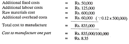
Therefore, the Company should make the part itself because manufacturing cost per part (Rs. 8.35) is less than the present cost to purchase (Rs. 8.50 by Re. 0.15 per part.).
Step # 3. Process Selection:
ADVERTISEMENTS:
Process selection determines how the product (or service) will be produced.
It involves:
1. Major technological choice:
a. Does technology exist to make the product?
b. Are there competing technologies among which we should choose?
c. Should the technology be developed in the country itself?
ADVERTISEMENTS:
d. Should innovations be licensed from foreign countries?
2. Minor technological choice:
Once the major technological choice is made, there may be a number of minor technological process alternatives available. The operations manager should be involved in evaluating alternatives for costs and for consistency with the desired product and capacity plans. Should the process be continuous, which is carried out for 24 hours a day in order to avoid expensive startups and shutdowns as used by steel and chemical industries.
An assembly line process on the other hand, follows the same series of steps as mass production but need not run for 24 hours a day e.g., automobile and ready-made garment industries. Job shop processes produce items in small lots, perhaps custom-made for a given customer/ market. Suppose, we make a job shop choice. The alternatives do not end here. For example, in a factory, the fabrication, joining together and finishing of two pieces of metal may represent only a minuscule part of creating a finished product.
There may be numerous ways of casting and molding, several ways of cutting, forming, assembly and finishing. Deciding on the best combination of processes in terms of costs and the total operations process can be difficult.
3. Specific component choice:
ADVERTISEMENTS:
a. What type of equipment (and degree of automation) should be used?
b. Should the equipment be specific purpose or general purpose?
c. To what degree should machines be used to replace human labor in performing and automatically controlling the work?
Computer-aided manufacturing (CAM) and industrial robots are being used increasingly in many manufacturing systems,
4. Process flow choice:
How should the product flow through the operations system? The final process-selection step determines how materials and products will move through the system. Assembly drawings, assembly Charts, route sheets and flow process charts are used to analyze process flow. Analysis may lead to re-sequencing, combining, or eliminating operations in order to reduce materials handling and storage costs. The four phases of process selection as discussed above are closely interrelated. In each phase, choices should be made to minimize the process operations costs.
Factors affecting process selection:
A process is necessary in order to shape, form, condition and join materials and components with, the help of machines and labour in order to convert raw material into a finished product. One should select the most economical process and sequence that satisfies the product specifications.
The selection of process depends upon:
(a) Current production commitments:
If enough work has already been allocated to more efficient equipment, the current work may have to be passed on to less efficient machines to complete the same in time.
(b) Delivery date:
An early delivery date may.
(i) Force the use of less efficient machines, and
(ii) Rule out the use of special tools and jigs as they will take time for design and fabrication.
(c) Quantity to be produced:
Small quantity will not probably justify the high cost of preparation and efficient set-ups. Thus, quite possible they may have to be made on less efficient machines and vice-versa.
(d) Quality standards:
Quality standards may limit the choice of making the product on a particular machine, etc.
Step # 4. Machine Capacity:
Capacity is a rate of output, a quantity of output in a given time, and it is the highest quantity of output that is possible during that time. Yet, capacity is at the same time a dynamic concept which is subject to being changed and managed. To some extent, it can be adjusted to meet fluctuating sales levels. Machine capacity may be defined as the time-available for work at a machine expressed in machine hours (minutes etc.).
For example, a machine may have a maximum capacity of 168 machine hours per week (7 days of 24 hours each). If overtime is worked, these extra-hours per week should be added to the normal machine capacity to find the planned machine capacity. It is now necessary to subtract time for maintenance (machine down time), finding the time preferably by reference to the maintenance plan and to a statistical record of past machine breakdowns.
Next, time must be allowed for idle machine time (waiting for work, no operator etc.) and for machine ancillary time (setting up, cleaning etc.). Finally, to find the time actually available for useful work, the machine running time must be corrected up or down, if the average performance in the factory is more or less than the standard performance used in fixing the standard times for work operations.
The final capacity achieved after making all these corrections is known as the Standard Machine running time and is generally very much less than the maximum 168 hours per week. Fig. 6.2 illustrates these various levels of machine capacity. It will be realized that it would be possible to check load against capacity at a number of these levels, by making the adjustment to correct for lost time, to either the load or the capacity.

Analysis of machine capacity:
The process of obtaining accurate information regarding the capacity of the available machines to produce the desired output is known as machine analysis. An objective of machine analysis is to obtain the answers to certain definite questions in regard to the use of manufacturing machines.
(1) How long will a certain machine take to perform its operation on a unit quantity of material?
(2) How many units of material can be processed on this machine per day, week or month?
(3) What is the maximum plant capacity per day for each process on each material?
The first of these three questions can be answered either:
(a) From standard data,
(b) By actual experiment and trial, or
(c) By reference to records of past performance.
The second question can be answered when the machining time and set-up time are known and when an adequate allowance has been made for the inevitable idle time. The third question is answered by aggregating the number of units which can be processed by similar machines to give the total plant capacity in units of product. From this information it is possible to determine the maximum capacity of each process and the plant as a whole. Machine load charts/showing the work ahead of each machine, can also be prepared.
Certain ratios related to this topic are:
![]()
![]()
![]()
![]()
Step # 5. Process and Equipment Selection Procedure:
The formal steps of the process and equipment selection procedure are:
1. Manufacturing operations:
Developing a general statement of the manufacturing operations to be performed.
2. Provisional Process:
Establishing a provisional process to provide each individual feature identified by the product designer. Several additional inputs are necessary before beginning the selection of the provisional process.
Specifically one must:
(a) Establish targets for facility and piece costs,
(b) Specify raw material,
(c) Determine hourly production volume preparatory to establishing machine capacity,
(d) Establish timing, and
(e) Select the provisional process.
As part of the selection of the provisional process, the manufacturing engineer will estimate the number of steps and consequent stations necessary to provide all the design features identified on the blueprint. This will require visualization of each individual sequence, an estimate of manpower required and a rough approximation of the necessary layout provisions to accommodate each step of the process.
No process should be selected with a confidence level below that acceptable to the particular management (0.92 is a suggested minimum).
(f) Based on the provisional process, the manufacturing engineer will develop judgemental costs of facilities and materials and, with the assistance of the industrial engineering function, will develop the preliminary piece cost of the components for the final assemblies.
3. Develop a list of process alternatives:
Upon completing the provisional processing steps, the manufacturing engineer should develop a list of process alternatives, particularly for those areas where detailed analysis of the preliminary processing has shown high cost, questionable performance, or places where the confidence level of achieving the requirements of the individual operator is judged to be marginal. Of assistance in developing these opportunities are the historical data relative to similar operations.
4. Provisional process:
A careful step-by-step comparison between each phase of the provisional process with each phase of alternative process will allow the manufacturing engineer to select the compromised position, which optimizes all the elements of cost, quality, flexibility and inherent risk.
All engineering management and manufacturing considerations being equal, production processes will be chosen on the basis of the most favourable return on investment or other financial criteria.
5. Upon completion of process selection:
Upon completion of process selection, it is communicated to the product engineering, industrial engineering, plant and maintenance engineering, industrial relations and finance departments. This will provide coordination and communication among all concerned which is essential for the successful adaptation of new technology to existing plant and staff.
6. Performing detailed processing:
When the process has been selected and communicated to all affected departments, the final detailed processing upon which all actions depend is initiated.
As the detailed processing proceeds, the manufacturing engineer will make extensive use of the body of engineering knowledge that resides with the machine and equipment suppliers.
As in the establishment of the provisional process, the starting point in establishing the detailed processing is to assemble the latest information relative to product design, production rate, facility cost and part cost targets. Detailed processing follows the same format as did the provisional processing, except that each element of the process will be completely identified and documented through the use of process estimate sheets.
Information is included on the source of the material for each process from rough stock to finished piece. The subsequent operation should be identified on each process Sheet SO that there can be an orderly part flow through each of the manufacturing operations.

Process sheet description:
To examine the required amount of processing documentation, a particular example — a machining operation-will be used. The basic principle involved is that the instructions detailed in the manufacturing engineering document, that is, the process sheet, be sufficiently explicit that operational personnel can perform every function necessary to produce the finished component and that operations can establish staffing and piece cost from which to judge operation efficiency during and after physically launching the operation.
The process sheet contains columns for recording the operation number, a description of operation, numbers and types of machines required, effective operational rates, labor distribution, and minute costs; provision is also made for recording facility and tool costs.
The process engineer will fill out those portions of the process sheet that relate to establishing the process and selecting the machinery; the plant engineer will enter data relating to the installation cost of the machinery; and the industrial engineer will appropriately ascertain and register the direct labor minutes of each operation, and so on.
The sample entry on the process sheet shows the manner in which the manufacturing engineer describes each step in manufacturing process. The engineer numbers and names the operation, namely, drill. He indicates the features, namely, the holes, and establishes their limits, that is, their size and depth. With this information, it is possible to identify the machine (s) required to carry out this specific step. In the example, the machine can be a single-spindle or multi-spindle and can be part of additional automation, that is, a transfer line or a dial machine.
All of this information is included on the process sheet. Numbers of machines required to meet the production volume and the space required complete the description of this individual process sheet. If fixtures or tools are required, they should be individually listed and costed as durable tools or special tools in the space provided. Each subsequent operation is identified in the exact detail until the part is finished.
Step # 6. Selection of Material, Jigs, etc.,:
It has become a subject requiring study, because selection of material has become complicated by the great increase not only in the kinds of materials but also in the various forms in which any one material may be available. Material should be of right quality and chemical composition as per the product specifications. Shape and size of material should restrict the scrap (i.e., material removed forgetting the product shape).
(a) Bill of material:
The most common method of analyzing a product into component parts is through the use of bills of material or specification sheets. Bill of material is a means of determining purchasing and production order requirements. It should indicate if the part is to be manufactured or purchased. The production-control department uses the bill of material to determine manufacturing and scheduling dates.
Process engineering uses it as a check list to complete their work. Methods engineering uses it in the preparation of time allowances for assembling operations. Accumulations are made by the stores department according to the bills of material. They in turn set up the shortage lists for use by expediters of the production-control department.
Releases by assembly units are made by the finished-stores department in accordance with the bills of material. The design of the bill of material varies slightly in minor details, depending upon the various uses made of it by individual companies.
The information usually required on the bill of material form includes:
(1) The product name
(2) Product code identification
(3) Sheet number
(4) Use
(5) Date of preparation
(6) Name/initials of preparer
(7) Name/initials of checker
(8) Item numbers
(9) Make/purchase designations
(10) Subassembly part numbers and names
(11) Quantity requirements and Bill of material is also known as parts list.
(12) Material used in each part.
Bill of material is also known as parts list. 
(b) Selection of jigs, fixtures and other special attachments:
These supporting devices are necessary:
1. To give higher production rate;
2. To reduce cost of production per piece.
(c) Selection of cutting tools and inspection gauges.
They, respectively, are necessary to:
1. Reduce production time;
2. Inspect accurately and at a faster rate.
(d) Process- layout:
Make the process- layout indicating every operation and the sequence in which each operation is to be carried out.
Process analysis:
Process Analysis means the study of the overall process in a factory (plant). It analyses each step of the manufacturing process and aims at improving the industrial operations. Process analysis aids in finding better methods of doing a job and this is achieved by eliminating unproductive and unnecessary elements of the process or through modified layout of facilities.
The process is analyzed with the help of Process Charts and Flow Diagrams.
Various steps involved in process analysis are:
(1) Select the process for analysis.
(2) Break down the process into operations and sub-operations.
(3) Construct a process chart and a flow diagram.
(4) Analyse the process chart and flow diagram by subjecting each and every step to questioning procedure.
(5) Reconstruct the process chart and flow diagram for the modified (proposed) procedure.
(6) Test the proposed method for all the advantages claimed for the same.
(7) Explain the new method to the workers and put it into operation.
Step # 7. Preparation of Documents:
Process chart:
A chart may be a diagram, a picture or a graph which gives an overall view of the situation, say a process. It helps visualizing various possibilities of alteration or improvement.
A chart representing a process may be called a Process Chart. A process chart records graphically or diagrammatically, in sequence, the operations connected with a process. The chart portrays the process with the help of a set of (process chart) symbols and aids in better understanding and examining the process with a purpose to improve the same.
Process charts symbols:
Charts are generally represented by symbols because symbols produce a better picture and quick understanding of the facts. Process charts use the following five basic symbols to record different types of events.

Outline (operation) process chart:
Fig. 6.5 shows an Outline Process Chart.

An outline process chart:
(a) Surveys and records an overall picture of the process and states only main events or steps sequence-wise,
(b) It helps visualising and comprehending the full process so that necessary improvements may be made if required,
(c) It shows relationship between the different activities.
(d) It considers only (main) operations and inspections, and thus it makes use of only two symbols,
(e) Each operation and inspection is numbered from the beginning to the end of the chart,
(f) Description of operations and inspections are written on the right-hand side of the symbols (refer Fig. 6.5) and
(g) Actually an outline process chart is the first step or the beginning of a detailed analysis.
Flow process charts:
A chart may be a diagram, a picture or a graph which gives an overall view of the situation, say a process. It helps visualising various possibilities of alteration or improvement.
A chart representing a process may be called a Process Chart. A process chart records graphically or diagrammatically, in sequence, the operations connected with a process. The chart portrays the process with the help of a set of (process chart) symbols and aids in better understanding and examining the process with a purpose to improve the same.
Operation planning and tooling requirements:
Operation planning is that stage in planning which marks the completion of routing at the process planning level. The operation planning is concerned with planning the details of the method to be used to complete each operation at its chosen work centre and with designing the necessary tooling.
Operations are divided into work elements. The record used to show the planned sequence of work elements is generally known as an operation sheet (Fig. 6.6.) It is in effect a record showing how an operation should be carried out.
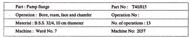

The purpose of the operation sheet is to record and communicate information that is essential for making each part. This is the sole determinant and criterion for the design of the form that will be used. It is intended to achieve a level of specification that can be costed, evaluated and altered in specific rather than in abstract terms. Operation sheets are prepared for each part, subassembly and assembly.
They indicate the route of the parts through the various departments, the sequence of required operations, the machines, special tools and gages needed, the time required to do each operation, the details of speeds, feeds etc. Operation sheets vary greatly from company to company. Simpler operation sheets list mainly the required operations and the machines to be used. As the next step, the process planner designs the tooling and calculates tooling requirements.
Once the tooling is designed, it must be recorded on some document, so that the correct tooling for any operation can be found when required; it is also necessary to make reference on the operation layout to this record. The record may consist of a simple list of tools for use in the tool store or, if production is in sufficient volume, it will pay to prepare special operation sheets which can be used by both the tool stores and by the machine setters. An example of these operation sheets is shown in Fig. 6.6.
The best way of numbering the tool kits for each operation is to use the part number, plus a suffix to show the operation concerned, or to use a classification system which will show the association between tooling kit and production operation in a similar manner. When this type of numbering system is used it is unnecessary to have a separate column on the operation layout for tooling; the tool-kit numbers are known. When the operation sheet has been accepted and finalized, real implementation of plans can begin. Machines, tools, gauges, fixtures and jigs required for fabrication can be assembled and inventoried.

An Operation and Route sheet, summarizes the operations required, the preferred sequence of operations, auxiliary tools required, estimated operation times etc. (Refer Fig. 6.8).
