Before starting to draw the network, following measures should be taken serially:
1. Prepare a list of the activities included in the project and their dependence on other activities.
2. Draft the network roughly, usually by soft pencil and an eraser on a large piece of paper.
3. The estimate of time required for each activity is made considering manpower and equipment’s available and in certain cases assumptions are based on statistical approach and experience.
ADVERTISEMENTS:
4. These time estimates are then written on each activity.
5. Then scheduling computations are done to get earliest and latest allowable start and finish times for each activity, to identify critical path and to indicate the amount of slack on non-critical paths.
6. Now this is prepared in final form for use in the field. Project is controlled by checking the progress against the schedule.
The construction of C.P.M. diagram can be explained by the following examples:
ADVERTISEMENTS:
Example 1:
For the construction of wall the complete process can be broken into the following operations:
(i) Brick laying A
(ii) Preparing mortar B
ADVERTISEMENTS:
(iii) Digging foundation C
(iv) Planning the foundation D
These above operation have not been written in a logical sequence. These operations can be denoted by the symbols ABCD.
The C.P.M. diagram can be drawn as shown in Fig. 28.35.
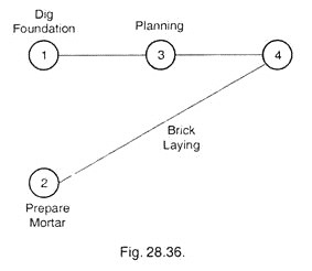
The operations D, C, B and A have now been shown in the logical sequence. From the study of these operations, it is found that preparing mortar is independent of digging foundation and planning operations. Therefore a modified C.P.M. diagram is drawn in Fig. 28.36.
In this figure numerals (1, 2, 3, etc.) are used commencing from the first column on the left and then proceeding towards right.
Example 2:
ADVERTISEMENTS:
A ladder is to be constructed. The various operations involved in it are:
(i) Fixing of Nails A
(ii) Cutting Wrings B
ADVERTISEMENTS:
(iv) Drilling holes in two Bamboos D
(v) Cutting two Bamboos E
Solution:
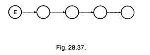
The operations are not given in logical order. There logical order will be according to Fig. 28.37.
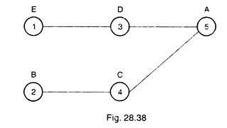
The modified network of Fig. 28.37 is shown in Fig. 28.38.
The cutting and drilling of the bamboos and wrings are different operations, and these are independent of each other. Therefore cutting two bamboos and cutting wrings can be started concurrently. Thus after the end of operation E, operation D can begin and similarly after the end of operation B, operation C can start.
After the end of operation C and D, the last operation of fixing nails can begin. Thus the network is drawn from left to right and each circle representing an operation is numbered from left to right. All the circles in the extreme left are first numbered and so on.
It is clear from the Fig. 28.38 that operation 5 can only begin when the operation 3 and 4 are over. Thus we can say that operation 1 immediately preceding operation 3, and operation 2 immediately precedes operation 4. Also the operation 3 and 4 must immediately precede the operation 5.
In the language of C.P.M., the operations 1 and 2 are called the pre-operations (or PRE- OPR) of 3 and 4 respectively. Similarly 3 and 4 both are the PRE-OPR of operation 5. Also 3 and 4 will be called post operations (POST-OPR) of operations 1 and 2 respectively, 5 is the POST- OPR of operation 3 and 4.
ADVERTISEMENTS:
Example 3:
Suppose we want to start a small scale factory in a shed available in an Industrial area in which workshop is to be prepared. First step is then to divide the project into operations.
The list of operations is given below, which is not in a logical order:
A = Machine foundation
B = Electric fitting
C = Repair of floor
ADVERTISEMENTS:
D = Installation of machines
E = Procure workshop building
F = Whitewash
G = Clean up
Solution:
Its logical order of operations should be E, A, D, B, F, C and G. (Refer Fig. 28.39).
If each operation is represented by a circle then this work can be executed in a better way as follows:
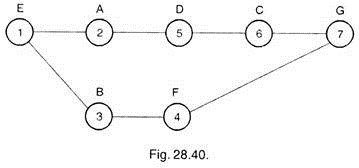
Sketch shown in Fig. 28.40 is drawn as per circle and line method in which circles represents the operation or activity and the line shows the relationship between the two activities. The operation on the left of each line should be completed before the starting of the operations on the right of the line.
Network shows that operation 3 and 4 are not affected by operations 2, 5 and 6. Hence the operations 3 and 4 can be conducted at the same time, when 2, 5 and 6 operations are being conducted.
This reduces the time to complete the project because after operation 1, operation 2 and 3 can be started simultaneously. Operations 6 and 4 should be completed before the beginning of the operation 7. In the final network, diagram operations should be represented by the numerals instead of alphabets.
Example 4:
ADVERTISEMENTS:
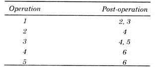
Construct the network diagram for which operations and post operations are given as under:
Solution:
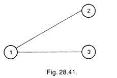
As no operation precedes operation 1, hence we shall start network from operation 1, keeping it in first vertical column. Operations 2 and 3 are post-operations of operation 1; hence these are kept in second vertical column as shown in Fig. 28.41.
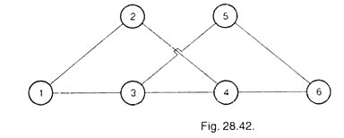
As operation 4 can be started when operation 2 is completed therefore, it will be kept in third vertical column. Operations 4 and 5 are the post-operations of operation 3 and can be started simultaneously after completion of operation 3, hence operations 4 and 5 both can be kept in the same third column. As operation 6 is the post-operation of operations 4 and 5, hence will be connected by both 4 and 5 and will be placed in the next column, i.e., in the fourth column as shown in Fig. 28.42.
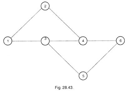
In Fig. 28.42, line connecting operations 3 and 5 crosses another line; hence it may be arranged in a better and clear form as shown in Fig. 28.43.
Sometimes, it is not possible to avoid it then the lines may cross each other but care should be taken that such lines should be as minimum as possible and clear to understand.
Example 5:
Example illustrates a case in which, operations and pre-operations are as under:
Solution:
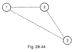
As the operation 1 is the first operation, hence network will be started by operation 1 denoted by the circle in first column. Operation 2 is the post-operation of 1 and therefore will be kept in second column.
Operation 3 has pre-operations 1 and 2; therefore operation 3 cannot be started unless operations 1 and 2 are complete. Hence operation 3 can be kept in third column, i.e. after operation 2, and not in second column immediately after operation 1. It is shown in Fig. 28.44.
Example 6:
Draw a network diagram for painting in a two storey building.
Solution:
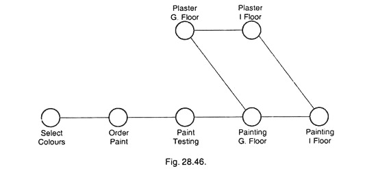
After dividing the project into some operations, network can be drawn as per Fig. 28.45.
If sufficient men, equipment’s and materials are available the network would be better to draw in the form as shown in Fig. 28.46 to reduce the timing required for selecting colours, ordering and testing paints and without waiting for the plaster on first floor, painting can be done on ground floor and in the mean-time plaster work on first floor will be completed and the painting on the same can be done. Therefore network shown in Fig. 28.46 is a better diagram from the point of view that it will save the time.
Example 7:
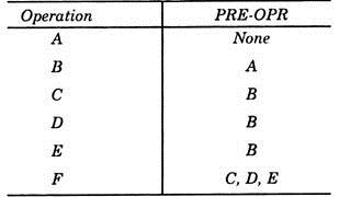
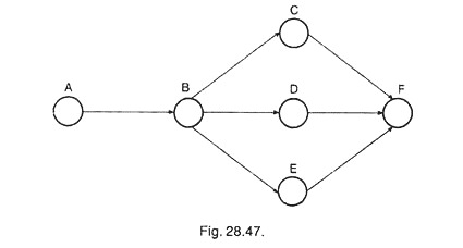
Draw the network diagrams for the project in which PRE-OPR or POST-OPR are given below:
The CPM network will be as in Fig. 28.47.
Example 8:
The example 7 for the above network diagram can also be framed in terms of POST-OPR as given under:
Example 9:
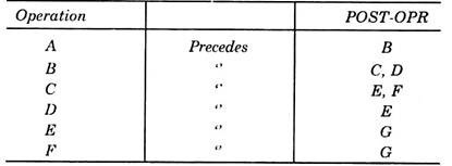
Draw the network for the following in which POST-OPRs are given:
Solution:
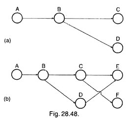
Fig. 28.48 (a) shows the sequence of operations A, B, C and D. Now the operation E is preceded by C and the operation F is also preceded by C. Hence, when the circles are drawn to show the operations E and F, the connecting lines of DE and CF intersect each other as shown in Fig. 28.48 (b).
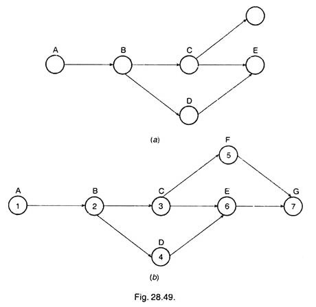
The intersection of lines DE and CF can be avoided by placing the operation Fin the fourth sequence above the operation E, as shown in Fig. 28.49 (a). Now the numbers may be placed in the operation circles beginning from left to right as shown in Fig. 28.49 (b).
As far as possible, the crossing of lines should be avoided. This makes the diagram less confusing and easier to understand. However, sometimes it may not be possible or desirable to eliminate the occurrence of such crossing lines. The numbering should be done starting from left and moving towards right, the first vertical sequence of operation being numbered first and then the second and so on.
Example 10:
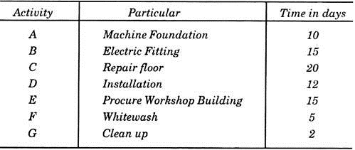
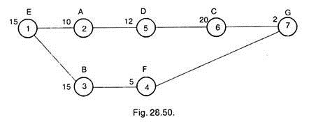
Following table shows the operation time in working days for different activities. Draw the critical path on the diagram.
Solution:
The above activities are drawn in the network as shown is Fig. 28.50. Each activity is represented by the numeral in the circle. Numbers of days are mentioned on the left corner of circle representing the operation.
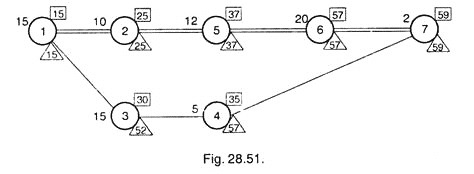
After drawing the network diagram, Earliest Finish for each operation is calculated and noted on the top right corner of the circle in the rectangles.
For the last operation 7, Latest time = Earliest finish time, i.e. 59 days in this case. From this value, Latest Finish time for other operations is calculated and written on the right bottom corner of the circle and inscribed in a triangle. For operations 2, 3, 4, 5 and 6 latest finish time is calculated by subtracting the working days required from the latest of post operation.
For operation 1, Latest Finish calculated by considering operation 2 is 25 – 10 = 15 days and by considering operation 3 is 52 – 15 = 37 days. In such case lower value is considered as the Latest Finish. Hence for operation 1, Latest Finish = 15 days.
Operations which are having Earlier Finish = Latest Finish are joined with double line and represent the critical path as shown in Fig. 28.51.

